7.1 KiB
| id | title | section | difficulty | estimated_time | prerequisites | objectives | tags |
|---|---|---|---|---|---|---|---|
| fund-05 | The Topological Phase Constraint | Fundamentals | intermediate | 25 | [fund-01 fund-02 fund-03 fund-04] | [Understand what a topological constraint is Derive the minimum achievable phase angle φ_Z,min Learn the critical capacitance ratio r = C_mut/C_sh Calculate φ_Z,min for typical Tesla coil geometries Understand R_opt_phase that achieves minimum phase] | [topology phase-constraint optimization mathematical-limit] |
The Topological Phase Constraint
Introduction
Can we make a spark look purely resistive (φ_Z = 0°)? Can we at least achieve the "balanced" -45° condition? Surprisingly, the circuit topology itself imposes fundamental limits on what phase angles are achievable, regardless of component values.
What is a Topological Constraint?
Definition: A limitation imposed by the structure of the circuit itself, independent of component values.
Example: Series RLC circuit
- Can only have impedance phase between -90° (pure C) and +90° (pure L)
- Cannot have φ_Z = +120° no matter what component values you choose
- This is a topological constraint
For spark circuits: The specific arrangement (R||C_mut) in series with C_sh creates a fundamental limit on how resistive the impedance can appear.
Deriving the Minimum Phase Angle
From our previous lesson, we have:
Y = [(G + jB₁) × jB₂] / [G + j(B₁ + B₂)]

where G = 1/R, B₁ = ωC_mut, B₂ = ωC_sh
The impedance phase is:
φ_Z = atan(-Im{Y}/Re{Y})
Question: For fixed C_mut and C_sh, which R value minimizes |φ_Z| (makes most resistive)?
Mathematical result: Taking derivative ∂φ_Z/∂G = 0 and solving:
G_opt = ω√[C_mut(C_mut + C_sh)]

Therefore:
R_opt_phase = 1 / [ω√(C_mut(C_mut + C_sh))]
At this resistance, the phase angle magnitude is minimized to:
φ_Z,min = -atan(2√[r(1 + r)])

where r = C_mut/C_sh (capacitance ratio)
Key insight: φ_Z,min depends only on the ratio r, not on absolute capacitance values or frequency!
The Critical Ratio r = 0.207
Let's find when φ_Z,min = -45° is achievable:
-45° = -atan(2√[r(1 + r)])
tan(45°) = 1 = 2√[r(1 + r)]
0.5 = √[r(1 + r)]
0.25 = r(1 + r) = r + r²
r² + r - 0.25 = 0

Using quadratic formula:
r = [-1 ± √(1 + 1)] / 2 = [-1 ± √2] / 2

Taking positive root:
r = (√2 - 1) / 2 ≈ 0.207
Critical insight:
- If r < 0.207: Can achieve φ_Z = -45° (with appropriate R)
- If r = 0.207: Minimum achievable phase is exactly -45°
- If r > 0.207: Cannot achieve φ_Z = -45° no matter what R you choose!
- If r ≥ 0.207: φ_Z,min is more negative than -45°
Typical Tesla Coil Values
Let's examine realistic scenarios:
Large topload, short spark:
C_mut = 10 pF, C_sh = 4 pF (2 feet)
r = 10/4 = 2.5

φ_Z,min = -atan(2√[2.5 × 3.5]) = -atan(2 × 2.96) = -atan(5.92) = -80.4°
Medium configuration:
C_mut = 8 pF, C_sh = 6 pF (3 feet)
r = 8/6 = 1.33

φ_Z,min = -atan(2√[1.33 × 2.33]) = -atan(2 × 1.76) = -atan(3.53) = -74.2°
Small topload, long spark:
C_mut = 6 pF, C_sh = 12 pF (6 feet)
r = 6/12 = 0.5

φ_Z,min = -atan(2√[0.5 × 1.5]) = -atan(2 × 0.866) = -atan(1.732) = -60.0°
Common range: r = 0.5 to 2.0, giving φ_Z,min ≈ -60° to -80°
Conclusion: For most Tesla coil geometries, -45° is mathematically impossible!
Worked Example: Calculate Minimum Phase Angle
Given:
- Frequency: f = 200 kHz
- C_mut = 8 pF
- C_sh = 6 pF
Find: (a) Capacitance ratio r (b) Minimum achievable phase angle φ_Z,min (c) R_opt_phase that achieves this angle
Solution:
Part (a): Capacitance ratio
r = C_mut / C_sh = 8 / 6 = 1.333
Part (b): Minimum phase angle
φ_Z,min = -atan(2√[r(1 + r)])
        = -atan(2√[1.333 × 2.333])
        = -atan(2√3.11)
        = -atan(2 × 1.764)
        = -atan(3.528)
        = -74.2°
Part (c): Resistance for minimum phase
ω = 2πf = 2π × 200×10³ = 1.257×10⁶ rad/s

R_opt_phase = 1 / [ω√(C_mut(C_mut + C_sh))]
            = 1 / [1.257×10⁶ × √(8×10⁻¹² × 14×10⁻¹²)]
            = 1 / [1.257×10⁶ × √(112×10⁻²⁴)]
            = 1 / [1.257×10⁶ × 10.58×10⁻¹²]
            = 1 / (13.30×10⁻⁶)
            = 75.2 kΩ
Interpretation:
- With r = 1.333, cannot achieve -45°
- Best possible is -74.2° (much more capacitive)
- This requires R = 75.2 kΩ
- Any other R value gives |φ_Z| > 74.2°
Understanding the Constraint Graphically
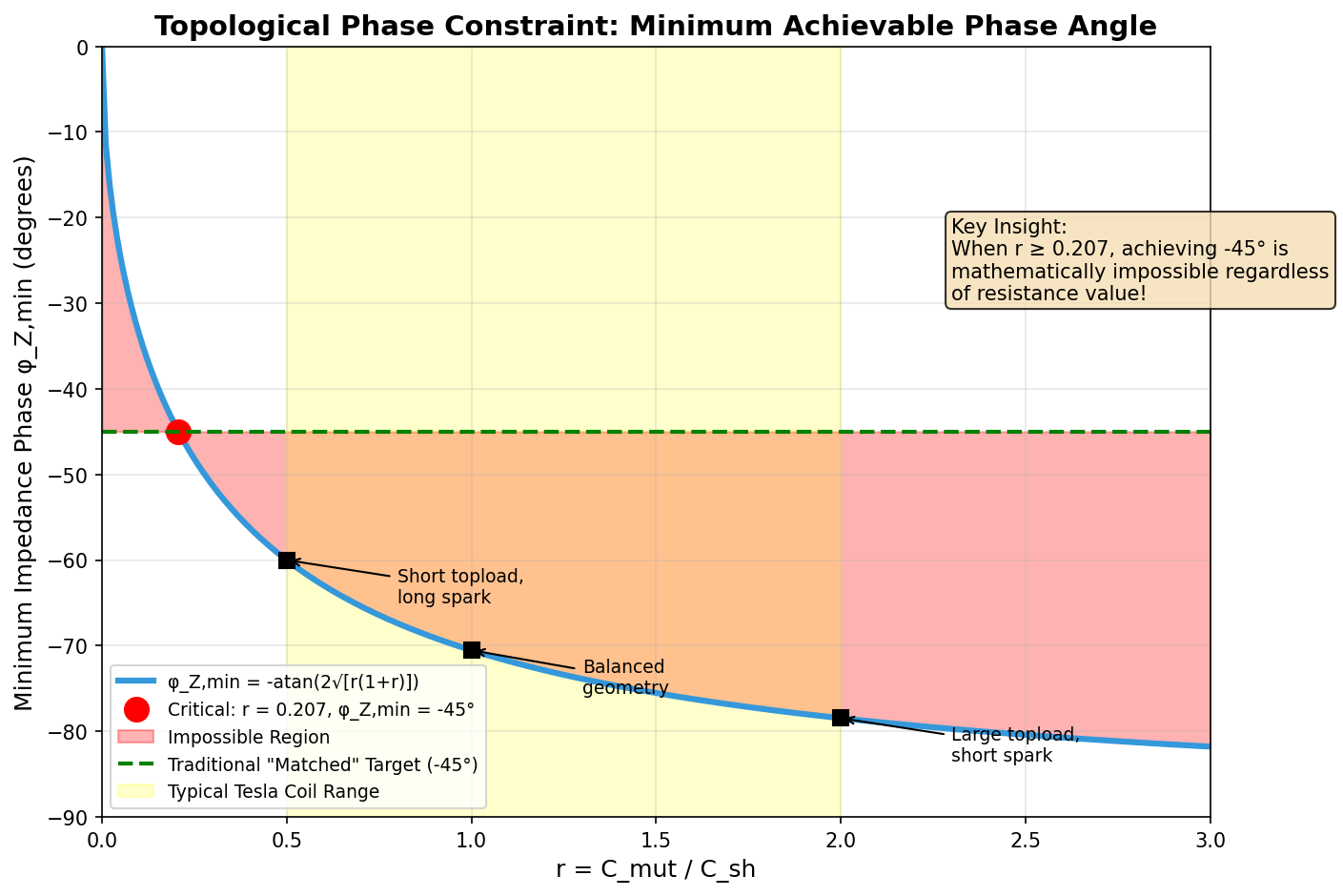
Graph characteristics:
- X-axis: r = C_mut/C_sh (log scale), range 0.1 to 10
- Y-axis: φ_Z,min (degrees), range -90° to -40°
- Curve: φ_Z,min = -atan(2√[r(1+r)])
Key features:
- r = 0.207 marked: φ_Z,min = -45° (horizontal dashed line)
- Region r < 0.207 (shaded): "Can achieve -45°"
- Region r > 0.207 (different shade): "Cannot achieve -45°"
- Typical Tesla coil range r = 0.5 to 2.0 highlighted
Example points:
- r = 0.1: φ_Z,min ≈ -35°
- r = 0.207: φ_Z,min = -45° (critical point)
- r = 0.5: φ_Z,min = -60°
- r = 1.0: φ_Z,min = -70.5°
- r = 2.0: φ_Z,min = -79.7°
- r = 5.0: φ_Z,min = -84.5°
Trends:
- Larger r → more capacitive minimum
- Large topload + short spark → high r → very capacitive
- Small topload + long spark → low r → less capacitive (but still > -45° usually)
Physical Interpretation
Why does this constraint exist?
The series connection of C_sh means current must flow through it to reach ground. This creates a capacitive voltage drop that can never be completely eliminated, no matter how you adjust R.
Analogy: Trying to make water flow uphill
- C_sh is like a mandatory uphill section in your pipe
- R adjusts resistance elsewhere, but can't remove the uphill section
- The uphill section imposes a minimum "difficulty" for flow
Engineering implications:
- Can't achieve purely resistive load (φ_Z = 0°)
- Usually can't achieve "balanced" -45° condition
- Must work with more capacitive phase angles
- Power transfer is inherently less efficient than with purely resistive load
Key Takeaways
- Topological constraint: Circuit structure limits achievable phase angles
- Minimum phase: φ_Z,min = -atan(2√[r(1 + r)]) where r = C_mut/C_sh
- Critical ratio: r = 0.207 allows exactly -45°
- Typical range: r = 0.5 to 2.0 → φ_Z,min ≈ -60° to -80°
- Optimal resistance: R_opt_phase = 1/[ω√(C_mut(C_mut + C_sh))]
- Most Tesla coils cannot achieve -45° due to geometry
Practice
{exercise:fund-ex-05}
Problem 1: Calculate r, φ_Z,min, and R_opt_phase for: f = 150 kHz, C_mut = 12 pF, C_sh = 8 pF.
Problem 2: A coil designer wants to achieve φ_Z = -45°. If C_sh = 10 pF (5-foot spark), what maximum C_mut is allowed?
Problem 3: Two coils have the same frequency and total capacitance (C_mut + C_sh = 20 pF). Coil A has r = 0.5, Coil B has r = 2.0. Which can achieve a more resistive phase angle? Calculate φ_Z,min for both.
Next Lesson: Why Not -45 Degrees?