6.9 KiB
| id | title | section | difficulty | estimated_time | prerequisites | objectives | tags |
|---|---|---|---|---|---|---|---|
| fund-03 | Admittance Analysis of the Spark Circuit | Fundamentals | intermediate | 30 | [fund-01 fund-02] | [Understand why admittance is preferred over impedance for parallel circuits Derive the total admittance formula for the spark circuit Calculate real and imaginary parts of admittance Convert between admittance and impedance representations Apply formulas to practical Tesla coil examples] | [admittance circuit-analysis complex-algebra formulas] |
Admittance Analysis of the Spark Circuit
Introduction
The spark circuit topology (R || C_mut in series with C_sh) requires careful analysis. While we could work entirely with impedances, using admittance simplifies the parallel combination and provides clearer insight into circuit behavior.
Why Use Admittance?
For the spark circuit topology (parallel R||C_mut, in series with C_sh), admittance simplifies calculations.
Parallel elements: Add admittances directly
Y_total = Y₁ + Y₂ + Y₃ + ...
vs impedances: 1/Z_total = 1/Z₁ + 1/Z₂ + ... (messy!)
Our circuit:
Y_mut_R = Y_Cmut + Y_R  (parallel: C_mut || R)
Then series with C_sh requires impedance: Z = Z_mut_R + Z_Csh
Then convert back: Y_total = 1/Z_total
Admittance makes the first step (parallel combination) trivial, and we only need to handle the series combination once.
Deriving the Total Admittance Formula
Let's work through the complete derivation step by step.
Step 1: Admittance of R and C_mut in parallel
Y_R = G = 1/R
Y_Cmut = jωC_mut = jB₁  (where B₁ = ωC_mut)

Y_mut_R = G + jB₁
Step 2: Convert to impedance for series combination
Z_mut_R = 1/(G + jB₁)
Step 3: Add impedance of C_sh in series
Z_Csh = 1/(jωC_sh) = -j/(ωC_sh) = 1/(jB₂)  (where B₂ = ωC_sh)

Z_total = Z_mut_R + Z_Csh
Z_total = 1/(G + jB₁) + 1/(jB₂)
Step 4: Find common denominator
Z_total = [jB₂ + (G + jB₁)] / [(G + jB₁) × jB₂]
Z_total = [G + j(B₁ + B₂)] / [jB₂(G + jB₁)]
Step 5: Invert to get admittance
Y_total = 1/Z_total = [jB₂(G + jB₁)] / [G + j(B₁ + B₂)]

Y_total = [(G + jB₁) × jB₂] / [G + j(B₁ + B₂)]
This is the fundamental admittance equation for the spark circuit.
Extracting Real and Imaginary Parts
To use this formula, we need to separate it into Re{Y} and Im{Y}.
Multiply numerator:
(G + jB₁) × jB₂ = jGB₂ + j²B₁B₂ = jGB₂ - B₁B₂
                = -B₁B₂ + jGB₂
So:
Y = [-B₁B₂ + jGB₂] / [G + j(B₁ + B₂)]
To separate real and imaginary parts, multiply numerator and denominator by complex conjugate of denominator:
Denominator conjugate: G - j(B₁ + B₂)
Denominator magnitude squared: G² + (B₁ + B₂)²
After algebra (multiply out and simplify):
Re{Y} = GB₂² / [G² + (B₁ + B₂)²]

Im{Y} = B₂[G² + B₁(B₁ + B₂)] / [G² + (B₁ + B₂)²]
These are the working formulas for calculating admittance from R, C_mut, C_sh.
Formula Summary
Given R, C_mut, C_sh, and frequency f:
Step 1: Calculate component values
ω = 2πf
G = 1/R
B₁ = ωC_mut
B₂ = ωC_sh
Step 2: Calculate admittance
Re{Y} = GB₂² / [G² + (B₁ + B₂)²]

Im{Y} = B₂[G² + B₁(B₁ + B₂)] / [G² + (B₁ + B₂)²]

Y = Re{Y} + j×Im{Y}
Step 3: Magnitude and phase
|Y| = √[Re{Y}² + Im{Y}²]
φ_Y = atan(Im{Y}/Re{Y})
Converting to Impedance
From Y = G_total + jB_total:
Z = 1/Y = 1/(G_total + jB_total)

Multiply by conjugate:
Z = (G_total - jB_total) / (G_total² + B_total²)

R_total = G_total / (G_total² + B_total²)
X_total = -B_total / (G_total² + B_total²)

Or directly:
|Z| = 1/|Y|
φ_Z = -φ_Y  (opposite sign!)
Worked Example: Complete Y and Z Calculation
Given:
- Frequency: f = 200 kHz → ω = 2π × 200×10³ = 1.257×10⁶ rad/s
- C_mut = 8 pF = 8×10⁻¹² F
- C_sh = 6 pF = 6×10⁻¹² F
- R = 100 kΩ = 10⁵ Ω
Find: Y_total (rectangular), Z_total (rectangular and polar)
Solution:
Step 1: Calculate component values
G = 1/R = 1/(10⁵) = 10⁻⁵ S = 10 μS
B₁ = ωC_mut = 1.257×10⁶ × 8×10⁻¹² = 10.06×10⁻⁶ S = 10.06 μS
B₂ = ωC_sh = 1.257×10⁶ × 6×10⁻¹² = 7.54×10⁻⁶ S = 7.54 μS
Step 2: Calculate Re{Y}
Re{Y} = GB₂² / [G² + (B₁ + B₂)²]

Numerator: 10 × (7.54)² = 10 × 56.85 = 568.5 μS²
Denominator: (10)² + (10.06 + 7.54)² = 100 + (17.6)² = 100 + 309.8 = 409.8 μS²

Re{Y} = 568.5 / 409.8 = 1.387 μS
Step 3: Calculate Im{Y}
Im{Y} = B₂[G² + B₁(B₁ + B₂)] / [G² + (B₁ + B₂)²]

Numerator inner: G² + B₁(B₁ + B₂) = 100 + 10.06×17.6 = 100 + 177.1 = 277.1 μS²
Numerator: 7.54 × 277.1 = 2089.3 μS³
Denominator: 409.8 μS² (same as before)

Im{Y} = 2089.3 / 409.8 = 5.10 μS
Step 4: Admittance result
Y_total = 1.387 + j5.10 μS
|Y| = √(1.387² + 5.10²) = √(1.92 + 26.01) = √27.93 = 5.28 μS
φ_Y = atan(5.10/1.387) = atan(3.68) = 74.8°
Step 5: Convert to impedance
|Z| = 1/|Y| = 1/(5.28×10⁻⁶) = 189 kΩ
φ_Z = -φ_Y = -74.8°

In rectangular:
R_total = |Z| × cos(φ_Z) = 189 × cos(-74.8°) = 189 × 0.263 = 49.7 kΩ
X_total = |Z| × sin(φ_Z) = 189 × sin(-74.8°) = 189 × (-0.965) = -182 kΩ

Z_total = 49.7 - j182 kΩ = 189 kΩ ∠-74.8°
Interpretation:
- Impedance is strongly capacitive (φ_Z = -74.8°)
- Equivalent resistance ≈ 50 kΩ (half of actual R due to capacitive divider)
- Large capacitive reactance dominates
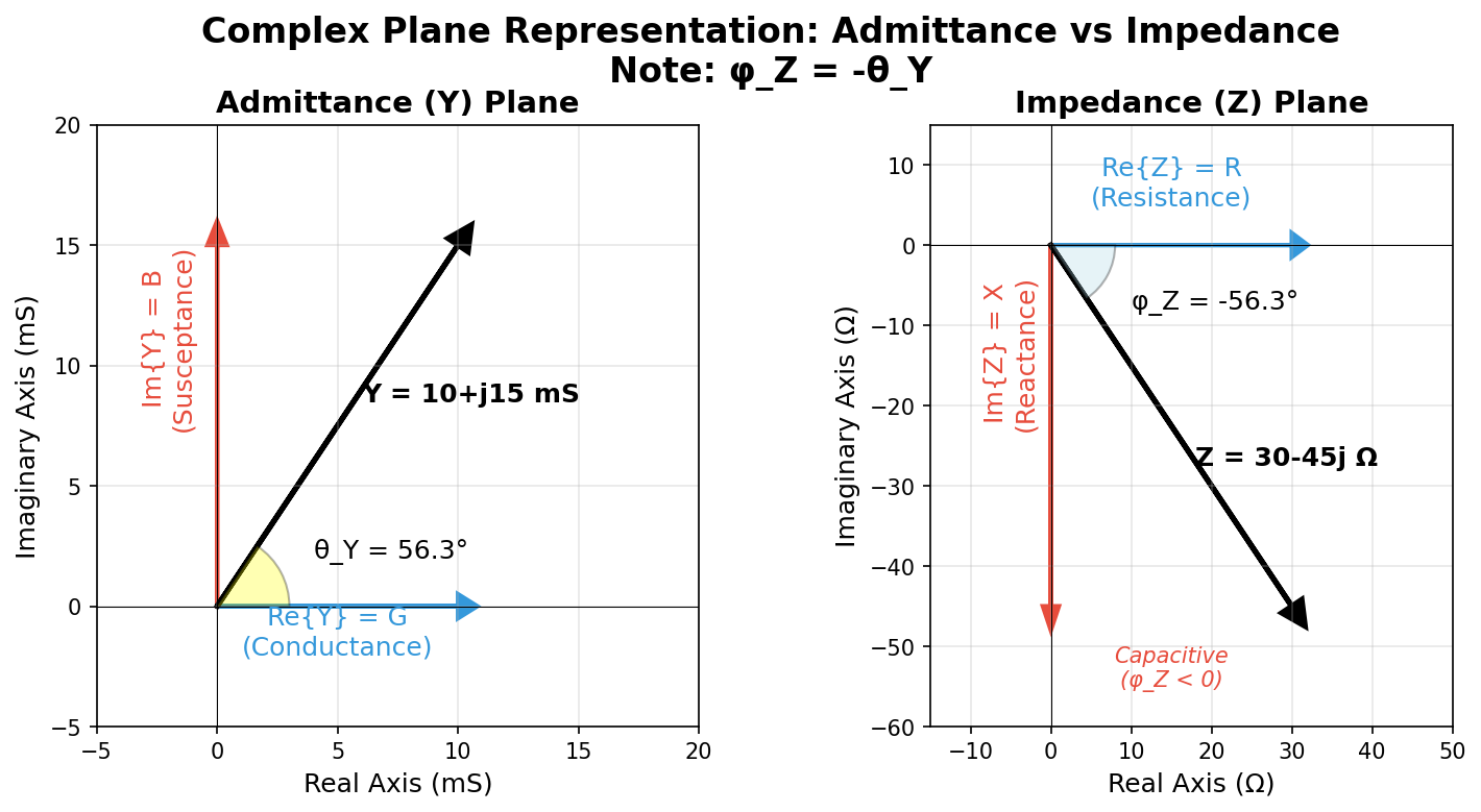
Visualization notes:
-
LEFT: Admittance plane (Y = G + jB)
- Point at (1.387, 5.10) μS
- Angle φ_Y = 74.8° from horizontal
- Positive B means capacitive in admittance
-
RIGHT: Impedance plane (Z = R + jX)
- Point at (49.7, -182) kΩ
- Angle φ_Z = -74.8° below horizontal
- Negative X means capacitive in impedance
-
Connection: Angles are opposite (φ_Z = -φ_Y), magnitudes invert (|Z| = 1/|Y|)
Key Takeaways
- Admittance simplifies parallel combinations: Y_parallel = Y₁ + Y₂ + ...
- Fundamental formula: Y = [(G + jB₁) × jB₂] / [G + j(B₁ + B₂)]
- Working formulas:
- Re{Y} = GB₂² / [G² + (B₁ + B₂)²]
- Im{Y} = B₂[G² + B₁(B₁ + B₂)] / [G² + (B₁ + B₂)²]
- Conversion: |Z| = 1/|Y| and φ_Z = -φ_Y
- Typical spark: strongly capacitive with large |Im{Y}| compared to Re{Y}
Practice
{exercise:fund-ex-03}
Problem 1: For f = 150 kHz, C_mut = 10 pF, C_sh = 8 pF, R = 80 kΩ, calculate Y_total (real and imaginary parts).
Problem 2: An admittance Y = 2.0 + j4.5 μS. Convert to impedance Z in both rectangular and polar forms.
Problem 3: Show algebraically that if R → ∞ (open circuit), the formula reduces to Y = jωC_mut × C_sh/(C_mut + C_sh), which is two capacitors in series.
Next Lesson: Phase Angles and Their Meaning